Kacher Brovina is original version generator of electromagnetic oscillations. It can be assembled using various active radioelements. At the moment, when assembling it, field or, less commonly, radio tubes (triodes and pentodes) are used. The Brovin Kacher was invented in 1987 by Soviet radio engineer Vladimir Ilyich Brovin as an element of an electromagnetic compass. Let's take a closer look at what kind of device this is.
Unknown capabilities of semiconductor elements
Brovin's kacher is a type of generator assembled on a single transistor and operating, according to the inventor, in abnormal mode. The device exhibits mysterious properties that date back to the research of Nikola Tesla. They do not fit into any of the modern theories of electromagnetism. Apparently, Brovin's kacher is a kind of semiconductor spark gap in which an electric current discharge passes through the crystalline base of the transistor, bypassing the formation stage (plasma). The most interesting thing about the operation of the device is that after a breakdown, the transistor crystal is completely restored. This is explained by the fact that the operation of the device is based on reversible avalanche breakdown, in contrast to thermal breakdown, which is irreversible for a semiconductor. However, only indirect statements are given as evidence of this mode of operation of the transistor. No one, except the inventor himself, has studied the operation of the transistor in the described device in detail. So these are just assumptions by Brovin himself. So, for example, to confirm the “black” mode of operation of the device, the inventor cites the following fact: they say, no matter what polarity the oscilloscope is connected to the device, the polarity of the pulses shown by it will always be positive.

Maybe kacher is a type of blocking generator?
There is also such a version. After all, the electrical circuit of the device strongly resembles an electrical pulse generator. Nevertheless, the author of the invention emphasizes that his device has a non-obvious difference from the proposed circuits. It provides an alternative explanation for the occurrence of physical processes inside the transistor. In a blocking oscillator, the semiconductor periodically opens as a result of the flow of electric current through the feedback coil of the base circuit. In quality, the transistor must be constantly closed in a so-called non-obvious way (since the creation of an electromotive force in the feedback coil connected to the base circuit of the semiconductor can still open it). In this case, the current generated by the accumulation of electrical charges in the base zone for further discharge, at the moment the threshold voltage value is exceeded, creates an avalanche breakdown. However, the transistors used by Brovin are not designed to operate in avalanche mode. A special series of semiconductors has been designed for this purpose. According to the inventor, it is possible to use not only bipolar transistors, but also field-effect and radio tubes, despite the fact that they have fundamentally different physics of operation. This forces us to focus not on research on the transistor itself in the quality, but on the specific pulse mode of operation of the entire circuit. In fact, Nikola Tesla was engaged in these studies.

Inventor about the device
In 1987, Brovin was designing a compass that would allow the user to determine the cardinal directions not through sight, but through hearing. He planned to use a tone that varied according to the location of the device relative to magnetic field planets. I used a blocking generator as a basis, improved it, and the resulting device was later called Brovin’s kacher. The reliable generator circuit turned out to be very useful: it was built according to classical principle, only a feedback circuit based on an inductive core based on amorphous iron is added. It changes the magnetic permeability at low strengths (for example, the magnetic field of a planet). The audio compass worked when the orientation changed, as intended.
Side effect
An analysis of the properties of the assembled circuit revealed some inconsistencies in its operation with generally accepted concepts. It turned out that the signals received at the electrodes of the semiconductor transistor, measured with an oscilloscope relative to the positive and negative poles of the voltage source, always had the same polarity. So, the npn transistor produced a positive signal at the collector, and pnp - a negative one. It is this effect that makes Brovin’s kacher interesting. The device circuit contains inductance, which during operation of the device has a resistance close to zero. The generator continues to operate even when a powerful permanent magnet approaches the core. The magnet saturates the core, as a result the blocking process must stop due to the cessation of transformation in the feedback circuit of the circuit. At the same time, no hysteresis was detected in the core; it could not be detected using Lissajous figures. The amplitude of the pulses at the collector of the transistor turned out to be five times higher than the voltage of the power source.

Kacher Brovina: practical application
The device is currently used as a plasma spark gap to create electric current pulses without arcing in experimental devices. The duo most often used is the Brovin kacher and This is due to the fact that the arc arising in the spark gap, in principle, serves as a broadband generator of electrical oscillations. This was the only device for creating high-frequency pulses available to Nikola Tesla. In addition, the inventor has created measuring devices based on the kacher, which make it possible to determine the absolute value between the generator and the radiation sensor.
Scientists shrug their shoulders
The above description of the device and the principle of its operation (and this is visible visually) contradict traditional science. The inventor himself openly demonstrates these contradictions; he asks everyone to work together to understand the paradoxical measurements of the parameters of his device. However, the position of openness on this issue has not yet led to any results; scientists cannot explain the physical processes in the semiconductor.

This is important
The description of the Brovin kacher effect in nearby space may turn out to be a way of reversing the spins of the atoms of surrounding substances. This is indicated by the author of the invention in an experiment with enclosing the device in a sealed glass vessel, from which the air was pumped out to reduce the pressure level in it. As a result of the experiment, there is no over-unit effect that would allow the device to be classified as not (with the exception of real experiments on energy transfer through a wire). This was first demonstrated by Nikola Tesla. However, possible incorrect power metering readings are explained by the pulsed, very inharmonious nature of the current flow in the power consumption circuits of the power supply. While measuring instruments tester type are designed for either direct or sinusoidal (harmonic) current.
How to assemble a Brovin kacher with your own hands
If, after reading the article, you are interested in this device, you can assemble it yourself. The device is so simple that even a novice radio amateur can make it. The Brovin Kacher (diagram shown below) is powered by a modified 12 V, 2 A network adapter and consumes 20 W. It converts an electrical signal into a 1 MHz field with an efficiency of 90%. For assembly we need a plastic pipe 80x200 mm. The primary and secondary windings of the resonator will be wound on it. The entire electronic part of the device is located in the middle of this pipe. This circuit is completely stable, it can work for hundreds of hours without interruption. The self-powered Brovin Kacher is interesting in that it is capable of lighting unconnected neon lamps at a distance of up to 70 cm. It is a wonderful demonstration device for a school or university laboratory, as well as a tabletop device for entertaining guests or for performing magic tricks.

Description of the electrical circuit assembly
The author of the invention recommends using a bipolar transistor KT902A or KT805AM (however, you can assemble a Brovin kacher on a field-effect transistor). The semiconductor element must be secured to a powerful radiator, having previously been lubricated with thermal conductive paste. You can additionally install a cooler. It is permissible to use constant resistors, and exclude capacitor C1 altogether. First, you should wind the primary winding with a wire of 1 mm (4 turns), then the secondary winding with a wire no thicker than 0.3 mm. The winding is wound tightly turn to turn. To do this, we attach its end to the beginning of the pipe and begin to wind it, coating the wire with PVA glue every 20 mm. It is enough to make 800 turns. We fix the end and solder an insulated conductor to it. The windings should be wound in one direction, it is important that they do not touch. Next, you need to solder a sewing needle into the upper part of the pipe and solder the end of the winding to it. Next, we solder the electrical circuit and place it together with the radiator inside the plastic pipe. This elementary device is Brovin’s kacher.
How to make an “ion engine”?
We start the assembled device with a minimum voltage of 4 volts, then gradually begin to increase it, while not forgetting to monitor the current. If you assembled a circuit using a KT902A transistor, then the streamer at the end of the needle should appear at 4 volts. It will increase as the voltage increases. When it reaches 16 volts it will turn into a “fluffy”. At 18 V it will increase to about 17 mm, and at 20 V the electrical discharges will resemble a real ion engine in operation.

Conclusion
As you can see, the device is simple and does not require large expenses. You can assemble it together with your child, because children love to play with “pieces of iron.” And here there is a double advantage: not only will the baby be busy, he will also gain confidence in his abilities. He will be able to participate in a school exhibition with his creation or show off to friends. Who knows, maybe, thanks to the assembly of such a basic toy, he will develop an interest in radio electronics, and in the future your child will be the author of some invention.
Or the Tesla transformer, as it is otherwise called. Videos from the YouTube channel Alpha Mods were used. The article contains three videos and simple circuit this device. The first video is about assembling the circuit, the second is about the case and testing the device. The third is effects. It is profitable to purchase radio components in this Chinese store.
This project will require a lot of winding wire. But you don't need to buy it at all. Use wire from transformers installed in power supplies, which, as a rule, lie unnecessarily at home. One of the coils has a thick but short wire. On the second coil the wire is thinner, but much longer. The primary winding is 0.2 mm, the secondary is 0.6 mm.
To get the wire, you need to disassemble the transformer by knocking on the housing. So the varnish is destroyed and the transformer falls into pieces. Now after the tape layer we see the winding wire.
We will wind the coil on a plastic pipe. Its size is 140×22. First, we need to make calculations to find the required length of wire that will be wound around the pipe. Calculations showed that we need to wind 31 meters of wire to get 450 turns on this pipe.
On the desktop, measure a distance of 1 meter. This is for measuring the wire. To wind the coil, you can build a device that will make the process semi-automatic. But, if you don’t mind your time, all this can be done manually.
Assembly
Notice that the plus goes through two places. First, it passes through a resistor and goes to the transistor. Secondly, it goes to the coil, and after it again goes to the transistor.
Kasher housing and Tesla coil testing
This container has a lid and a silicone gasket on it. The container will be upside down. Now you can make markings for future parts and make holes for them. On the side there will be a power connector. Given the soft material of the container, holes can be made very easily.
An elastic band is used to secure the reel. It will be put on the reel and pressed to the bottom with a nut and washer. Now the reel sits perfectly in its place and at the same time has the ability to be slightly cushioned. We will pass the wires inside so that it is unnoticeable.
The primary coil can be wound in different ways. The legs can be made from small metal spikes. The Tesla coil will definitely need cooling, so that also needs to be done.
Lastly, repainting and finally assembly. A layer of thermal paste is applied to the transistor, and it is placed on the radiator. For the torus, a ping pong ball and foil are used. You need to wrap the ball in foil. The most important thing is that the secondary coil wire touches the torus.
The power supply from an old 32 Volt printer was used.
Eventually the box is closed and the project is officially finished. This device can be used to transmit energy wirelessly. It is almost impossible to control this energy with this device, but you can play with it. For example, holding 220 volt light bulbs in your hands, which will burn by receiving electricity through the air. You can turn off the light on the table with one touch of your hand.
More effects of the assembled Brovin kacher
Preface
This spring, I was faced with the task of creating a set of generators to test the stability of equipment under conditions of strong electrical discharges. In addition to the transistor-based HF generators that are familiar to me, which provide good HF field strength nearby, I needed a small high-voltage source. This is where I remembered the quality device of the Soviet radio engineer Vladimir Ilyich Brovin - a simple device that allows me to get the high voltage I need.
I assembled my first kacher back in the early 2000s. It was a fairly powerful device almost one meter high, producing a dense beam of corona discharges. It was a dangerous thing... Hair began to move a couple of meters from it... But now I need a compact, small coil that is safe to use. After examining the materials and parts I had, I got to work.
Device diagram
The quality circuit has reached our times practically unchanged and is a blocking oscillator on a single transistor. Currently, there are many variants of circuits for this device assembled using lamps, bipolar and field-effect transistors, but I settled on the simplest “classical” circuit.

“Classic” scheme of Brovin’s quality
Parts and materials
The device is based on two main elements - an inductively coupled coil and a transistor for generating oscillations. The transistor was chosen D1761(the first one that caught my eye and had the required parameters). As a coil frame, I used a piece of polypropylene plastic pipe with a diameter of 32 mm and a length of 140 mm. In addition, in the bins there was a coil with PEV-2 wire, 0.15 mm in diameter, which I used in the manufacture of the quality device.
Assembling the device
Stepping back 20 mm from the end of the tube, I wound 650 turns of wire (winding - turn to turn in one layer, without overlaps). In this case, the length of the coil winding L2 was 105 mm.
I soldered the mounting wires to the ends of the wire and secured them inside the tube to prevent damage to the winding. The entire winding was covered with two layers of acrylic varnish. I soldered a steel needle to the upper terminal of the coil and brought it out through a decorative plastic plug. I secured the coil body on the circuit board for easy setup and placement of the coil. L1.
![]()
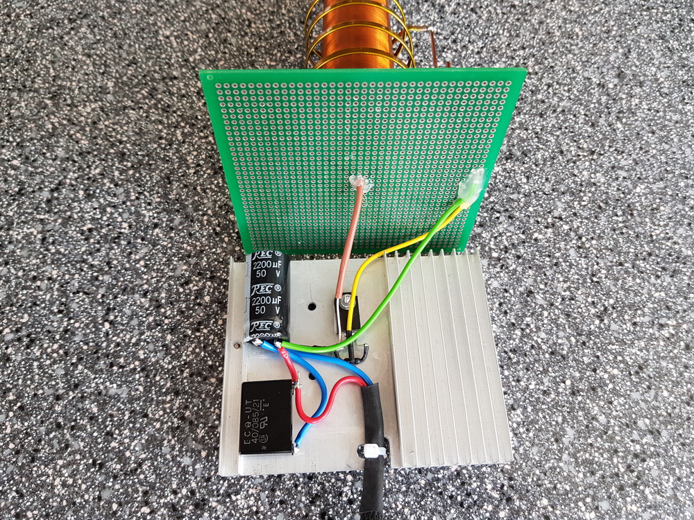
Brovin quality components![]()
![]()
Reel L1 I made it from a copper busbar, 3 mm wide. It is wound on a mandrel D 45 mm, only 5 turns with a small pitch. Here you need to remember that the direction of winding the turns is the same as that of coil L2. If the winding directions do not coincide, the generator will consume current, but there will be no high voltage at the output!
To connect the L1 coil to the circuit, I installed a screw connector. It turned out simple and convenient.
Since the pump circuit contains only 5 parts, I assembled it using a hinged installation, placing the parts on the radiator body.
Device setup
A correctly and carefully assembled generator from serviceable components almost always starts working. To obtain the maximum voltage, you can try to change the position and number of turns of the L1 coil, focusing on the size of the streamer and the current consumed. In my case, with a supply voltage of 24 volts, the coil consumes 0.85 A. For my task, this is optimal. In some cases, it may be necessary to select resistors in the base circuit.

Since my streamer is not very large, to visually indicate the operation of the coil and the presence of high voltage, I added a small neon light bulb to the body of the coil.

Conclusion
The Brovin Kacher is an easy-to-replicate and interesting device for studying high-voltage discharges in various environments. The very principle of its operation is interesting and mysterious... After all, the voltages generated by the high-voltage coil, and these are thousands and tens of thousands of volts, do not damage the transistor, although they are directly applied to the base of this semiconductor device.
In principle, there is a scientific explanation for this mystery (and even more than one), but still, the very principle of operation of the device remains a subject of debate among scientists and experimenters, as well as enthusiasts engaged in searches Free Energy and those studying the legacy of Nikola Tesla. Perhaps you will be the one to solve this riddle...
Hello, dear readers and site guests!
Today we will talk about Brovin’s quality. This interesting device was invented in 1987 by Soviet engineer Vladimir Ilyich Brovin. The kacher was part of the electromagnetic compass, but today it is most often collected out of interest. According to Brovin, the scheme is not too complicated, and with its help you can get the most interesting visual effects.
Kacher is a reactivity pump, which is what this device does. According to legend, it produces more energy than it consumes, which is highly doubtful, but not too difficult to verify. One of the most interesting qualities of the kacher is that the Brovin kacher scheme is extremely simple and accessible even to beginners. It can be assembled using or, but radio tubes - pentodes and triodes - are also suitable for this.
The “mysterious” properties that Brovin’s kacher demonstrates go back to the famous research of Nikola Tesla. They do not fully fit into any of the modern theories of electromagnetism, and this is precisely why Brovin’s powerful kacher interested me. In essence, the Brovin Kacher is a kind of semiconductor spark gap, the discharge in which passes through the crystalline base of the transformer, skipping the stage of the appearance of an electric arc. And the most curious thing is that after the breakdown the crystal returns to normal.
The fact is that in such devices it is not thermal breakdown that occurs, but avalanche breakdown. But here it is worth noting that detailed studies of the quality were carried out only by the engineer Brovin himself. After him, such a device was repeatedly assembled by amateurs, but the principles of its operation were not studied. For example, to confirm the status of a quality player, Brovin recommends connecting an oscilloscope to it. Whatever polarity it is connected to, the pulses will always show positive polarity. While Brovin’s kacher scheme has not found any practical application, it has not been subjected to serious research. And amateurs can only explore the simplest manifestations of the work of a caster, which is what we will do next.

I will not dwell in detail on the device diagram, because it is well-known and publicly available. Let me just note that the camera consists of three main parts: the camera itself, the power supply and the breaker. A chopper, or control unit, is used to regulate the frequency and duty cycle of the pulses emitted by the pump. They enter the transistor, which opens and closes the junction between current and source in accordance with the pulse clock. When opened, current flows and closes the pump circuit to the power supply - this creates a pulse. During the short period of time during which the opening occurs, a spark runs through the terminal.
To describe it in a nutshell, we can say that when current flows in two directions to the transistor and the chopper, voltage appears on the power supply. The breaker turns on, sends a pulse to the gate of the transistor, the gate opens the junction, current passes through the switch and closes the circuit.
So, what do we need to assemble a powerful Brovin kacher?
- Hands - even the most inexperienced or crooked ones will do.
- Wire with a cross-section of 0.25 mm - you can use wire from a transformer.
- Bipolar transistor p-p-p(kt805AM, kt808, kt805B, KT902A and other similar transistors that can be obtained from almost any Soviet electronics.)
- A pair of resistors.
- High capacity capacitor (1000 -10000 uF)
- Power supply DC voltage(from 12 to 30 volts with a current strength of at least 1-1.5 amperes.)
This is the so-called standard set; if you do not have any element, you can always find a replacement for it.
For example, the chopper can be replaced with any generator that produces rectangular pulses. Changing any circuit element values by ten to thirty percent will not prevent the circuit from working. Of course, it should be remembered that working with other indicators of Brovin’s quality will be somewhat different. I recommend choosing a generator frequency within 150 hertz.
The Brovin Kacher is connected to a regular 220 volt network. For protection purposes, I advise you to install a five-amp fuse. To power the car, you will need 310 volts, that is, the 220 volts received from the outlet will need to be straightened. To do this, you can take a diode bridge with indicators of at least ten amperes and five hundred volts. The breaker will need another diode bridge - 50 volts and one ampere. In addition, it must be bypassed with a capacitor.
The Brovin kacher himself may have deviations of parts performance of 20 percent from the nominal ones. The field transient can be replaced with another one, but in this case I advise you to use a similar, but more powerful one. The circuit capacitor will need to be adjusted independently; the optimal adjustment level is from half to one microfarad.
As for the coil, you will need two wires for the windings. For the primary, a wire of two squares is used, but the winding will have very few turns. The secondary winding can be made with PLSHO or any other similar wire. The main thing is to get the required number of turns. Some advise making only 500 revolutions, others say that at least one and a half thousand are required, if not all two. We will focus on the average in the region of a thousand turns. You can use glue, varnish, or epoxy resin to wrap it so it doesn't fall apart if you don't wrap it tightly enough. In any case, a lost winding can greatly hinder you.
We take a choke with a resistance from fifteen to forty ohms. You can remove this from LDS lamps. If you can’t find just such a choke, you can replace it with a resistor, the resistance of which is within the same limits, and the power exceeds a thousand watts.
Now we begin to assemble Brovin's kacher. First you need to make the primary coil. To do this, take any tube with a diameter of 4-7 centimeters and use copper wire large section or copper tube. We make four turns, not too tightly, since after this you will need to remove the tube. Now we remove the tube and stretch the wire so that the height of the winding is ten to fifteen centimeters.
The secondary coil should be three times higher. For it, we take a thin winding wire and wind it around a plastic tube for about 1000 revolutions. I did this by hand so it took a little time to create the coil. If you've ever done this, you know what a tedious process it is. You can speed up the work somewhat by using an electric screwdriver. But in this case, it is very important to calculate the number of revolutions per minute and the time it takes to create the winding in order to make the required number of turns. The reel is ready. To prevent it from going astray, you can apply glue in places - it will hold it in place and allow you to work without extreme caution. We install the primary coil around the bottom of the secondary coil.
We assemble the remaining elements according to the diagram. The tube needs to be fixed vertically, so it is best to glue its lower part to the base. You can take an unnecessary disk for this, but I chose a wooden plank - a more convenient option. Now let's check the diagram. If something doesn’t work, first try swapping the contacts of the primary coil; in addition, the direction of the primary and secondary windings is important - they should be wound in the same direction. If this does not help, check the transistor. It may be faulty. Also check the conductivity of the coils - there may be no contact somewhere.
I also advise you not to be afraid of the position and number of turns of the thick wire - it should be located at the base of the coil, but for me it is almost in the middle. Change its position until the effect appears. This should help, no other problems should arise with such a simple circuit.
Now let's move on to setting up the assembled camera. To do this, we adjust the tuning resistor R1. I installed radiators on the transistors - they get very hot, so it’s better to protect the device from surprises.
This assembly option is not the only one. We can try another Brovin kacher, developed by the engineer himself or his followers.

Such circuits use two or three coils and a variety of transistors. I found the option of a camera with a three-color LED, three coils and a start button interesting. The power supply for the Brovina kacher circuit is obtained from 1.2 volt AA batteries. The diameter of the coils is 5 centimeters. For the first and third coils we make 60 turns, and for the second – 30. This is not so much, so it is not difficult to make the coils by hand. The transistor can be taken Kt315, 9014, S9013 or 9018.
In this circuit, it is important to think about the location of the coils. The LED lights best if you place the second and third coils next to each other. But even as the third coil approaches the first, the glow becomes stronger. If all three coils are placed side by side, the glow will be strongest, but in this case you will have to work hard to find the correct position of the first coil - it must be turned a certain way. In this embodiment, the glow appears only on the red and green LED crystals. After replacing the first coil with a choke, the blue crystal began to glow.
Here it would be useful to mention a few important rules (I hope you haven’t started collecting them yet):
- You cannot touch the discharges with your hands. If you decide to do this, it won't hurt that much, but you may end up with a pretty bad burn.
- Make sure that there are no pets in the room during experiments.
- It is better to put mobile phones, computers and other electronics away. An electromagnetic pulse can seriously damage them.
- It is not recommended to experiment for a long time.
Now we can check the kacher in operation. The effects kacher Brovina creates are quite beautiful. The thing is that, according to the principle of operation, the kacher is a simple high-frequency generator operating on a single transistor. Feedback in it is carried out by turning on the emitter-base transition in series. This circuit is the inductor we assembled earlier. It resonates at a frequency determined by the number of turns and interturn capacitances. The generation frequency range is quite large - from 3 to 100 MHz.
The powerful kacher Brovina produces the following discharges:
- Streamers are branched channels with a dim glow; they contain free electrons and ionized gas atoms. This is the visible ionization of the air, which is created by the high-pressure field of the jet.
- Arc discharge - appears when the power of the transformer is high enough, if a grounded object is brought close to its terminal. An arc may appear between this object and the terminal. If you touch the terminal with this object and slowly move it away, the arc will stretch. However, here I advise you to be extremely careful; it is better to make do with experiments with streamers.
To get the “ion engine” effect, you need to run the Brovin kacher at a minimum voltage of four volts. Then we gradually begin to increase the voltage, but do not forget that you need to control the current. I assembled a circuit using a KT902A transistor, the streamer appeared already at a voltage of 4 volts. By increasing the voltage, we see that the streamer becomes larger. We bring it up to 16 volts and get this “fluffy” thing. At 18 volts, the size of the streamers reaches approximately 17 millimeters, and at 20 we observe the effect of an ion engine in operation, which is what we now planned to achieve.
So, what else can you do using the assembled Brovin kacher?
What you should not do is bring cameras, phones or other gadgets near it. There is a powerful electromagnetic field around the camera, so any electronics that fall into it can burn out. If you want to make sure of this, the easiest way is to bring a light bulb into the field. It's best to take energy saving lamp. It begins to glow no worse than if it were plugged into an outlet. If you have a lamp at home daylight, you can enter it into the field - the effect will be approximately the same. If you take a regular incandescent lamp, it will glow differently than usual. The glow appears colored - most of all orange and purple. It looks like a magic ball that you have probably seen in gift shops or souvenir shops. If you have a quartz resonator, you can see a rather interesting glow effect.
It is difficult to find practical application for such a device as the powerful Brovin Kacher. In fact, I assembled the kacher solely as an experiment. Other enthusiasts are usually guided by the same reason. Perhaps you will be the one who will find the assembled camera some more useful application. If you succeed, be sure to share with us your build option and how you can benefit from this interesting device.
Write comments, additions to the article, maybe I missed something. Take a look at, I will be glad if you find something else useful on mine.
A very interesting device called the “Brovin Kacher” is very popular among radio amateurs. With its help you can observe spectacular corona discharges, lightning, and plasma arcs. Many people on the Internet call the kacher a Tesla coil, but these are two completely different devices with different operating principles. In this article we will talk specifically about the Brovin quality device, perhaps the simplest high-voltage device that you can think of.
Brovin's quality scheme

The circuit is extremely simple, containing only one transistor, a pair of resistors and a pair of capacitors. Capacitors serve to filter the supply voltage, one of them should be electrolytic with a large capacity (470-2200 µF), and the second ceramic or film with a low capacitance (0.1-1 µF), to smooth out high-frequency interference. Two resistors form a voltage divider, one of them should have a small resistance (150-200 Ohms), and the second should have about 10-20 times more resistance. In this case, a trimming resistor can be placed in series with the high-resistance resistor to adjust the quality to the maximum discharge length. There is a mounting location for it on the printed circuit board attached to the article. Almost any powerful transistor can be used in the circuit n-p-n structures. Transistors KT805, KT808, KT809 have proven themselves well. You can also experiment with field ones and install, for example, IRF630, IRF740. The length of the discharges largely depends on the choice of transistor. The transistor must be installed on the radiator, because it stands out large number heat. L1 in the diagram is the primary coil, and L2 is the secondary coil, the high-voltage discharge is removed from it.
Device board
The payment is made using the LUT method, a printable file is attached. Terminal blocks are provided on the board to connect power wires and coil outputs.


Download the board:
Manufacturing of a secondary (high voltage) coil
First of all, you need to make a secondary coil. With it, everything is simple and specific - the more turns, the greater the voltage, and, accordingly, the longer the discharges. You can use enameled copper wire with a cross section of 0.1 - 0.3 mm. It is very convenient to use as a frame for the secondary winding sewer pipe, the optimal diameter is 5-7 cm. You need to wind the wire turn to turn, as carefully as possible. It is advisable to use a single piece of wire so that there are no joints. But if the wire breaks during the process, it’s okay, you can solder the torn piece to it, carefully insulate it and continue winding the turns, it will work in any case.

To speed up the winding process, you can install the pipe on two supports on the left and right so that it rotates freely on them. This will make winding the wire much easier. If you need to leave during work, you can secure the tip of the wire with tape, then you can come back, peel off the tape and continue winding. Under no circumstances should you let go of the tip of the wire, otherwise the tension will disappear, the turns will diverge and you will have to start all over again.

After the coil is wound, the turns of wire must be fixed to the pipe. It is best to use a transparent varnish, then the reel will look very beautiful. I coated the coils with regular wax, it did the job, now it will be much more difficult to accidentally damage the thin wire.

A regular wire should be soldered to the lower end of the wire and carefully fixed at the edge of the pipe.

At the upper edge of the pipe there is a so-called “terminal” - the place from which the corona discharge will “emanate”. It is advisable to make it sharp, then the discharge will be concentrated at the tip of the needle. I secured a bolt to the edge of the pipe, and screwed a dart tip onto the bolt, as can be seen in the photo. The secondary coil is ready.

Making the Primary Coil
The primary coil contains 2-5 turns of thick copper wire, with a cross-section of 1.5 - 2.5 mm. It should be located around the secondary coil, its diameter should be 2-3 cm larger. For the frame of the primary coil, you can again use a sewer plastic pipe, you just need to take a piece of pipe with a diameter and length greater than for the secondary one. At a distance of 10 cm from the top of the pipe, two holes are drilled through which the copper wire is threaded. The length of the discharge strongly depends on the number of turns, so their number is selected experimentally.

The wire from the turns themselves must be brought to the bottom of the coil, passing them inside the pipe. Be sure to fix it with glue. The primary coil is ready.

Assembling the Brovin quality
After the coils are wound, you can put everything together. Two round pieces with holes in the center are cut out of penoplex. The secondary coil should fit tightly into the central hole, and the outer diameter of the workpieces should match the diameter of the primary coil.

We place the round blanks inside the large pipe, and then insert the secondary coil into them. If necessary, you need to fix them with glue. The wire from the secondary coil must be routed to the bottom of the large pipe.


Two holes are drilled at the bottom of the large pipe, one for the power connector, the second for the toggle switch.

Now all that remains is to connect the board to the power supply, placing a toggle switch in the positive wire gap, and connect the coil leads.

When all wires are connected, you can check the functionality of the device. Carefully apply voltage to the board. If a small light appears on the terminal, it means the camera is working. If the kacher refuses to work even when the supply voltage increases, the leads of the primary coil should be swapped. Now you can experiment with the number of turns in the primary coil, move the coils relative to each other, finding a position at which the discharge will be maximum. The power supply voltage range of the camera is very wide - a small discharge appears already at 12 volts. As the voltage increases, it increases, and along with it, the heat dissipation on the transistor increases. Therefore, it is imperative to monitor the temperature of the radiator, because an overheated transistor will not work for a long time.
The last thing that remains is to install the board with the radiator inside the large pipe, in its lower part, and place the toggle switch with the connector in the already drilled holes.


This camera looks very impressive even when turned off. You can touch the corona discharge with your finger, it is quite safe, because the current from such a discharge flows along the surface of the skin without penetrating inside. This effect is called the skin effect, it occurs due to the high frequency of the camera. During long-term operation, a large amount of ozone is released, so you should turn on the power generator only in ventilated areas. Also, do not forget about the strong electromagnetic radiation that is created around the device. It can damage other electronic devices, so you should not leave phones, cameras, or tablets nearby. The electromagnetic field created is so strong that gas-discharge (or, more simply put, energy-saving) light bulbs light up on their own near the coil.