Somehow recently I came across a diagram on the Internet that was very simple block power supply with voltage regulation. The voltage could be adjusted from 1 Volt to 36 Volt, depending on the output voltage on the secondary winding of the transformer.
Take a close look at the LM317T in the circuit itself! The third leg (3) of the microcircuit is connected to capacitor C1, that is, the third leg is INPUT, and the second leg (2) is connected to capacitor C2 and a 200 Ohm resistor and is an OUTPUT.
Using a transformer, from a mains voltage of 220 Volts we get 25 Volts, no more. Less is possible, no more. Then we straighten the whole thing with a diode bridge and smooth out the ripples using capacitor C1. All this is described in detail in the article on how to obtain constant voltage from alternating voltage. And here is our most important trump card in the power supply - this is a highly stable voltage regulator chip LM317T. At the time of writing, the price of this chip was around 14 rubles. Even cheaper than a loaf of white bread.
Description of the chip
LM317T is a voltage regulator. If the transformer produces up to 27-28 volts on the secondary winding, then we can easily regulate the voltage from 1.2 to 37 volts, but I would not raise the bar to more than 25 volts at the transformer output.
The microcircuit can be executed in the TO-220 package:

or in D2 Pack housing

It can pass a maximum current of 1.5 Amps, which is enough to power your electronic gadgets without voltage drop. That is, we can output a voltage of 36 Volts with a current load of up to 1.5 Amps, and at the same time our microcircuit will still output 36 Volts - this, of course, is ideal. In reality, fractions of volts will drop, which is not very critical. When there is a large current in the load, it is more advisable to install this microcircuit on a radiator.
In order to assemble the circuit, we will also need a variable resistor of 6.8 Kilo-Ohms, or even 10 Kilo-Ohms, as well as a constant resistor of 200 Ohms, preferably from 1 Watt. Well, we put a 100 µF capacitor at the output. Absolutely simple scheme!
Assembly in hardware
Previously, I had a very bad power supply with transistors. I thought, why not remake it? Here is the result ;-)
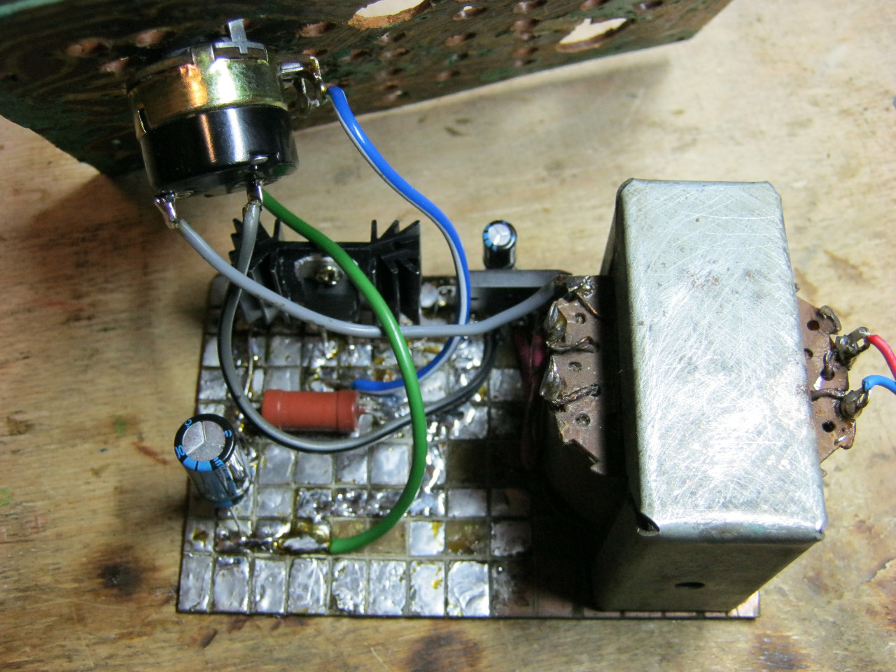
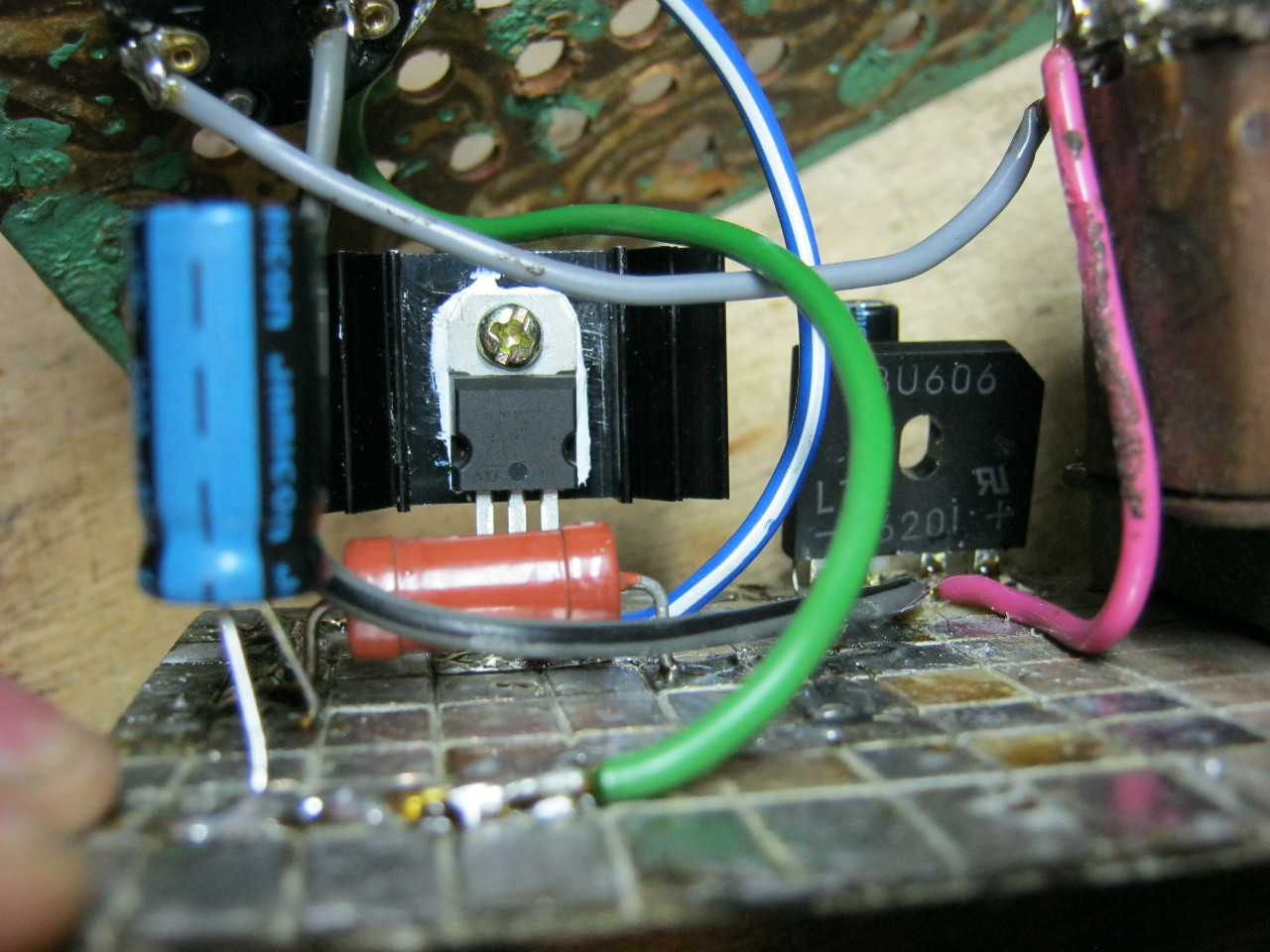
Here we see the imported GBU606 diode bridge. It is designed for a current of up to 6 Amps, which is more than enough for our power supply, since it will deliver a maximum of 1.5 Amps to the load. I installed the LM on the radiator using KPT-8 paste to improve heat transfer. Well, everything else, I think, is familiar to you.
And here is an antediluvian transformer that gives me a voltage of 12 volts on the secondary winding.

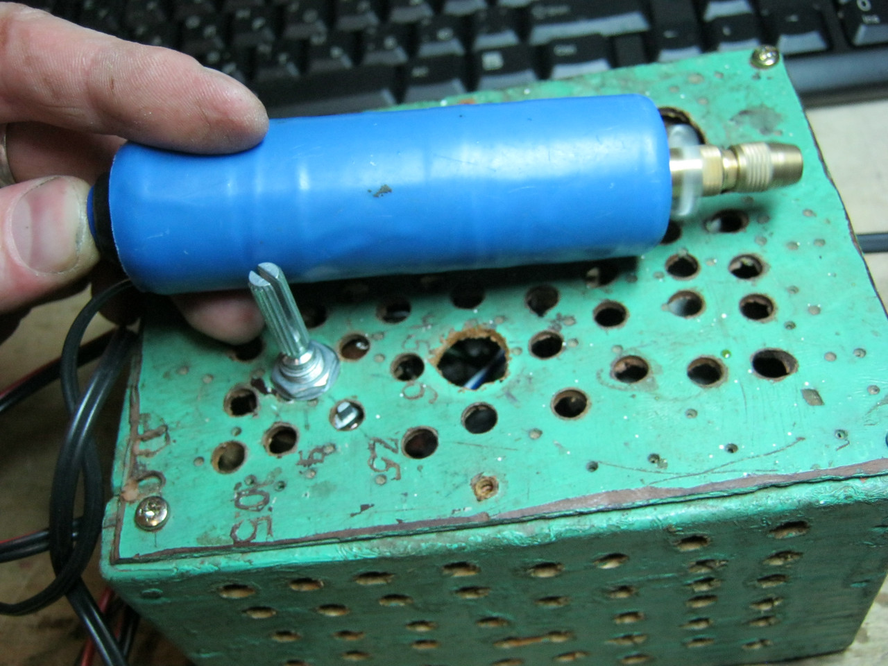
We carefully pack all this into the case and remove the wires.

How do you like it? ;-)

The minimum voltage I got was 1.25 Volts, and the maximum was 15 Volts.


I set any voltage, in this case the most common are 12 Volts and 5 Volts


Everything works great!
This power supply is very convenient for adjusting the speed of a mini drill, which is used for drilling circuit boards.
Analogues on Aliexpress
By the way, on Ali you can immediately find a ready-made set of this block without a transformer.

Too lazy to collect? You can buy a ready-made 5 Amp for less than $2:

You can view it at this link.
If 5 Amps is not enough, then you can look at 8 Amps. It will be enough for even the most seasoned electronics engineer:

Power supplies DC needed not only by radio amateurs. They have a very wide scope of application, and therefore most home craftsmen use them to one degree or another. This article describes the main types of voltage converters, their characteristic differences and applications, and how to make a simple power supply with your own hands.
Doing it yourself will save you a lot of money. Once you understand the device and operating principle, you can easily repair this device.

Applications
These devices have a very wide range of applications. Let's look at the main uses. To save battery life, low-voltage power tools are connected to homemade power supplies. Such devices are used for connecting LED lighting devices, installing lighting in rooms with high humidity and danger of electric shock, and for many other purposes not directly related to radio electronics.


Device classification
Most power supplies convert AC mains voltage of 220 volts into DC voltage of a given value. Moreover, the device is characterized by a large list of operating parameters that must be taken into account when purchasing or designing.

The main operating parameters are output current, voltage and the ability to stabilize and adjust the output voltage. All these converters are classified into two large groups according to the conversion method: analog and pulse devices. These groups of power supplies have strong differences and are easily distinguished from the photo at first glance.

Previously, only analog devices were produced. In them, voltage conversion is carried out using a transformer. Collecting such a source is not difficult. Its scheme is quite simple. It consists of a step-down transformer, a diode bridge and a stabilizing capacitor.

Diodes convert AC voltage to DC voltage. The capacitor further smoothes it out. The disadvantage of such devices is their large dimensions and weight.

A 250-watt transformer weighs several kilograms. In addition, the voltage at the output of such devices can change due to external factors. Therefore, to stabilize the output parameters in such devices, special elements are added to the electronic circuit.

High-power power supplies are manufactured using transformers. It is advisable to use such devices for charging car batteries or for connecting electric drills to save the life of lithium batteries.

The advantage of such a device is the galvanic isolation between the two windings (with the exception of autotransformers). The primary winding connected to the high voltage network has no physical contact with the secondary winding. A reduced voltage is generated on it.

Energy transfer is carried out using magnetic field alternating current in the metal core of the transformer. If you have minimal knowledge in radio electronics, it is easier to assemble a classic adjustable power supply using a transformer with your own hands.


With the development of electronic technology, it has become possible to produce cheaper semiconductor voltage converters. They are very compact, light in weight and have a very low price. Thanks to this, they became market leaders. Every apartment uses several different power supplies.

Unfortunately, most modern devices do not have galvanic isolation from the power supply. Because of this, quite often people die who use the device while charging a cell phone or other equipment and at the same time take a bath or wash their face.

If safety precautions are followed, there is no danger to a person. These devices are quite low in cost and when they break down, they often do not try to repair them, but purchase a new device. However, if you understand the circuits and operating principles of switching power supplies, you can easily both repair such a power supply and assemble a new device.

Switching power supplies
Let's look at the design and operating principle of switching power supplies. In such devices, the alternating mains voltage is converted into high-frequency voltage at the input. To transform high-frequency currents, it is not large transformers that are required, but miniature electromagnetic coils. Therefore, such converters easily fit into small housings. For example, they can easily be placed in the plastic socket of an energy-saving lamp.


The layout of such a power supply in a small device does not cause any problems. For reliable operation, it is necessary to provide the possibility of cooling heating elements on special metal radiators electronic circuit. The converted voltage is rectified using high-speed diodes and smoothed at the output filter.

The disadvantage of such devices is the inevitable presence of high-frequency interference at the output of the converter, despite the presence of special filters. In addition, pulsed devices use special output voltage stabilization circuits.


The switching power supply can be purchased as a separate unit, ready for installation in the device. You can also assemble this device yourself using widely available diagrams and instructions for assembling power supplies.

It should be taken into account that self-assembly may be more expensive than a purchased product purchased online in the Asian market. This may be due to the fact that electronic components are sold at a higher markup than the manufacturer's markup in China for the assembly of the product and its delivery. In any case, having understood the structure of such devices, it will be possible not only to assemble such a device yourself, but also, if necessary, to repair it. Such skills will be very useful.

If you want to save money, you can use switching power supplies from personal computers. Often in out of order personal computer there is a working block. They require minimal modification before use.

Such power supplies have idle protection. They must be under load at all times. Therefore, in order to avoid shutdown, a constant resistance is included in the load. Such modernized units are used primarily to power household power tools.

DIY photo of power supplies


Most modern electronic devices practically do not use analog (transformer) power supplies; they are replaced by pulsed voltage converters. To understand why this happened, it is necessary to consider design features, as well as the strengths and weaknesses of these devices. We will also talk about the purpose of the main components of pulsed sources and provide a simple example of an implementation that can be assembled with your own hands.
Design features and operating principle
Of the several methods of converting voltage to power electronic components, two that are most widespread can be identified:
- Analog, the main element of which is a step-down transformer, in addition to its main function, it also provides galvanic isolation.
- Impulse principle.
Let's look at how these two options differ.
PSU based on a power transformer
Let's consider a simplified block diagram of this device. As can be seen from the figure, a step-down transformer is installed at the input, with its help the amplitude of the supply voltage is converted, for example, from 220 V we get 15 V. The next block is a rectifier, its task is to convert the sinusoidal current into a pulsed one (the harmonic is shown above the symbolic image). For this purpose, rectifying semiconductor elements (diodes) connected via a bridge circuit are used. Their operating principle can be found on our website.
The next block performs two functions: it smoothes the voltage (a capacitor of appropriate capacity is used for this purpose) and stabilizes it. The latter is necessary so that the voltage does not “drop” when the load increases.
The given block diagram is greatly simplified; as a rule, a source of this type has an input filter and protective circuits, but this is not important for explaining the operation of the device.
All the disadvantages of the above option are directly or indirectly related to the main design element - the transformer. Firstly, its weight and dimensions limit miniaturization. In order not to be unfounded, we will use as an example a step-down transformer 220/12 V with a rated power of 250 W. The weight of such a unit is about 4 kilograms, dimensions 125x124x89 mm. You can imagine how much a laptop charger based on it would weigh.
Secondly, the price of such devices is sometimes many times higher than the total cost of the other components.
Pulse devices
As can be seen from the block diagram shown in Figure 3, the operating principle of these devices differs significantly from analog converters, primarily in the absence of an input step-down transformer.
 Figure 3. Block diagram pulse block nutrition
 Let's consider the operating algorithm of such a source:
- Power is supplied to the surge protector; its task is to minimize network interference, both incoming and outgoing, that arises as a result of operation.
- Next, the unit for converting sinusoidal voltage into pulsed constant voltage and a smoothing filter come into operation.
- At the next stage, an inverter is connected to the process; its task is related to the formation of rectangular high-frequency signals. Feedback to the inverter is carried out through the control unit.
- The next block is IT, it is necessary for automatic generator mode, supplying voltage to the circuit, protection, controller control, as well as the load. In addition, the IT task includes ensuring galvanic isolation between high and low voltage circuits.
Unlike a step-down transformer, the core of this device is made of ferrimagnetic materials, this contributes to the reliable transmission of RF signals, which can be in the range of 20-100 kHz. A characteristic feature of IT is that when connecting it, the inclusion of the beginning and end of the windings is critical. The small dimensions of this device make it possible to produce miniature devices; an example is the electronic harness (ballast) of an LED or energy-saving lamp.

- Next, the output rectifier comes into operation, since it works with high-frequency voltage; the process requires high-speed semiconductor elements, so Schottky diodes are used for this purpose.
- At the final phase, smoothing is performed on an advantageous filter, after which voltage is applied to the load.
Now, as promised, let’s look at the operating principle of the main element of this device – the inverter.
How does an inverter work?
RF modulation can be done in three ways:
- pulse-frequency;
- phase-pulse;
- pulse width.
In practice, the last option is used. This is due both to the simplicity of implementation and to the fact that PWM has a constant communication frequency, unlike the other two modulation methods. A block diagram describing the operation of the controller is shown below.
The device operation algorithm is as follows:
The reference frequency generator generates a series of rectangular signals, the frequency of which corresponds to the reference one. Based on this signal, a sawtooth U P is formed, which is supplied to the input of the comparator K PWM. The UUS signal coming from the control amplifier is supplied to the second input of this device. The signal generated by this amplifier corresponds to the proportional difference U P ( reference voltage) and U PC (regulating signal from the feedback circuit). That is, the control signal UUS is, in fact, a mismatch voltage with a level that depends on both the current on the load and the voltage on it (U OUT).
This implementation method allows you to organize a closed circuit that allows you to control the output voltage, that is, in fact, we are talking about a linear-discrete functional unit. Pulses are generated at its output, with a duration depending on the difference between the reference and control signals. Based on it, a voltage is created to control the key transistor of the inverter.
The process of stabilizing the output voltage is carried out by monitoring its level; when it changes, the voltage of the control signal U PC changes proportionally, which leads to an increase or decrease in the duration between pulses.
As a result, the power of the secondary circuits changes, which ensures stabilization of the output voltage.
To ensure safety, galvanic isolation between the supply network and the feedback is necessary. As a rule, optocouplers are used for this purpose.
Strengths and weaknesses of pulsed sources
If we compare analog and pulse devices of the same power, the latter will have the following advantages:
- Small size and weight due to the absence of a low-frequency step-down transformer and control elements that require heat removal using large radiators. Thanks to the use of high-frequency signal conversion technology, it is possible to reduce the capacitance of the capacitors used in the filters, which allows the installation of smaller elements.
- Higher efficiency, since the main losses are caused only by transient processes, while in analog circuits a lot of energy is constantly lost during electromagnetic conversion. The result speaks for itself, increasing efficiency to 95-98%.
- Lower cost due to the use of less powerful semiconductor elements.
- Wider input voltage range. This type of equipment is not demanding on frequency and amplitude; therefore, connection to networks of various standards is allowed.
- Availability of reliable protection against short circuits, overload and other emergency situations.
The disadvantages of pulse technology include:
The presence of RF interference is a consequence of the operation of the high-frequency converter. This factor requires the installation of a filter that suppresses interference. Unfortunately, its operation is not always effective, which imposes some restrictions on the use of devices of this type in high-precision equipment.
Special requirements for the load, it should not be reduced or increased. As soon as the current level exceeds the upper or lower threshold, the output voltage characteristics will begin to differ significantly from the standard ones. As a rule, manufacturers (even recently Chinese ones) provide for such situations and install appropriate protection in their products.
Scope of application
Almost all modern electronics are powered from blocks of this type, as an example:


Assembling a switching power supply with your own hands
Let's consider the circuit of a simple power supply, where the above-described principle of operation is applied.

Designations:
- Resistors: R1 – 100 Ohm, R2 – from 150 kOhm to 300 kOhm (selectable), R3 – 1 kOhm.
- Capacitances: C1 and C2 - 0.01 µF x 630 V, C3 -22 µF x 450 V, C4 - 0.22 µF x 400 V, C5 - 6800 -15000 pF (selectable), 012 µF, C6 - 10 µF x 50 V, C7 – 220 µF x 25 V, C8 – 22 µF x 25 V.
- Diodes: VD1-4 - KD258V, VD5 and VD7 - KD510A, VD6 - KS156A, VD8-11 - KD258A.
- Transistor VT1 – KT872A.
- Voltage stabilizer D1 - microcircuit KR142 with index EH5 - EH8 (depending on the required output voltage).
- Transformer T1 - a w-shaped ferrite core with dimensions 5x5 is used. The primary winding is wound with 600 turns of wire Ø 0.1 mm, the secondary (pins 3-4) contains 44 turns Ø 0.25 mm, and the last winding contains 5 turns Ø 0.1 mm.
- Fuse FU1 – 0.25A.
The setup comes down to selecting the values of R2 and C5, which ensure excitation of the generator at an input voltage of 185-240 V.
It took one day to develop this power supply, during the same day it was implemented, and the whole process was filmed on a video camera. A few words about the scheme. This is a stabilized power supply with output voltage regulation and current limitation. Schematic features allow you to reduce the minimum output voltage to 0.6 Volts, and the minimum output current to around 10 mA.
Despite the simple design, this power supply is inferior even to good laboratory power supplies costing 5-6 thousand rubles! The maximum output current of the circuit is 14 Amperes, the maximum output voltage is up to 40 Volts - no longer worth it.
Quite smooth current limitation and voltage regulation. The block also has fixed protection against short circuits; by the way, the current protection can also be set (almost all industrial designs lack this function), for example, if you need the protection to operate at currents up to 1 Ampere, then you just need to set this current using trigger current setting regulator. The maximum current is 14A, but this is not the limit.


As a current sensor, I used several 5 watt 0.39 Ohm resistors connected in parallel, but their value can be changed based on the required protection current, for example - if you are planning a power supply with a maximum current of no more than 1 Ampere, then the value of this resistor is around 1 Ohm at power 3W.
In case of short circuits, the voltage drop on the current sensor is sufficient to trigger the transistor BD140. When it opens, the lower transistor, BD139, also triggers, through the open junction of which power is supplied to the relay winding, as a result of which the relay is triggered and the working contact opens (at the output of the circuit). The circuit can remain in this state for any amount of time. Along with the protection, the protection indicator also works. In order to remove the block from protection, you need to press and lower the S2 button according to the diagram.
Protection relay with a 24 Volt coil with a permissible current of 16-20 Amps or more.
In my case, the power switches are my favorite KT8101 installed on the heat sink (there is no need to additionally isolate the transistors, since the key collectors are common). You can replace the transistors with 2SC5200 - a complete imported analogue or with KT819 with the GM index (iron), if desired, you can also use KT803, KT808, KT805 (in iron cases), but the maximum output current will be no more than 8-10 Amperes. If a unit is needed with a current of no more than 5 Amps, then one of the power transistors can be removed.
Low-power transistors like BD139 can be replaced with a complete analog - KT815G (you can also use KT817, 805), BD140 - with KT816G (you can also use KT814).
There is no need to install low-power transistors on heat sinks.
In fact, only a control (adjustment) and protection circuit (working unit) is presented. As a power supply, I used modified computer power supplies (series connected), but you can use any network transformer with a power of 300-400 watts, a secondary winding of 30-40 Volts, a winding current of 10-15 Amps - this is ideal, but you can use transformers and less power.
Diode bridge - any, with a current of at least 15 Amps, voltage is not important. You can use ready-made bridges; they cost no more than 100 rubles.
In 2 months, over 10 such power supplies were assembled and sold - no complaints. I assembled exactly such a power supply for myself, and as soon as I didn’t torture it, it was indestructible, powerful and very convenient for any task.
If anyone wants to become the owner of such a power supply unit, I can make it to order, contact me at This email address is being protected from spambots. You must have JavaScript enabled to view it., the video assembly tutorials will tell you the rest.